
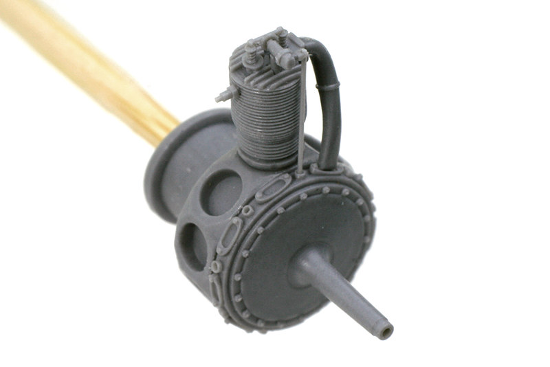
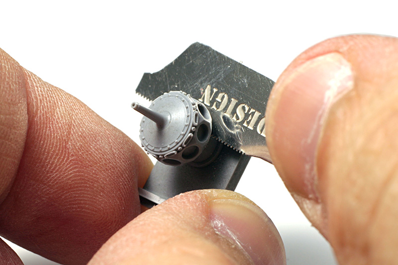
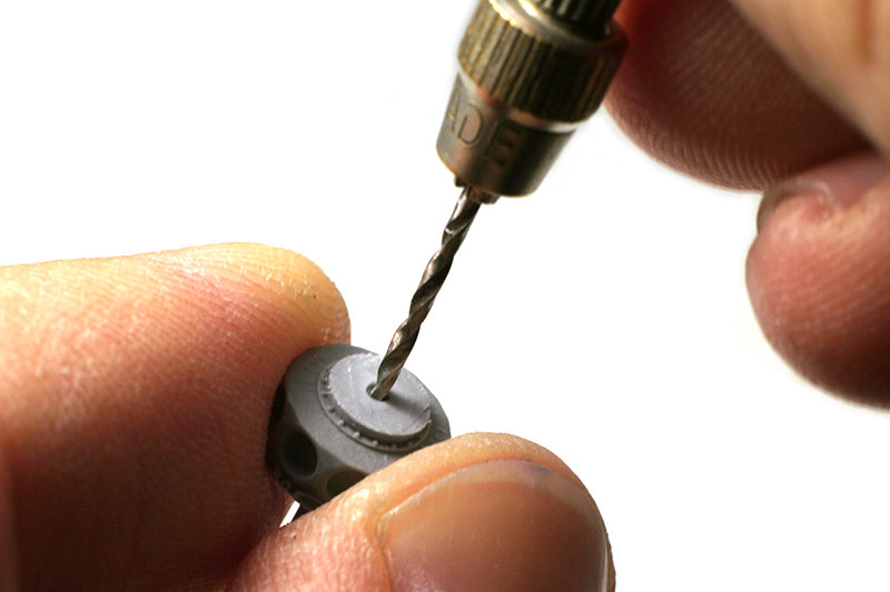
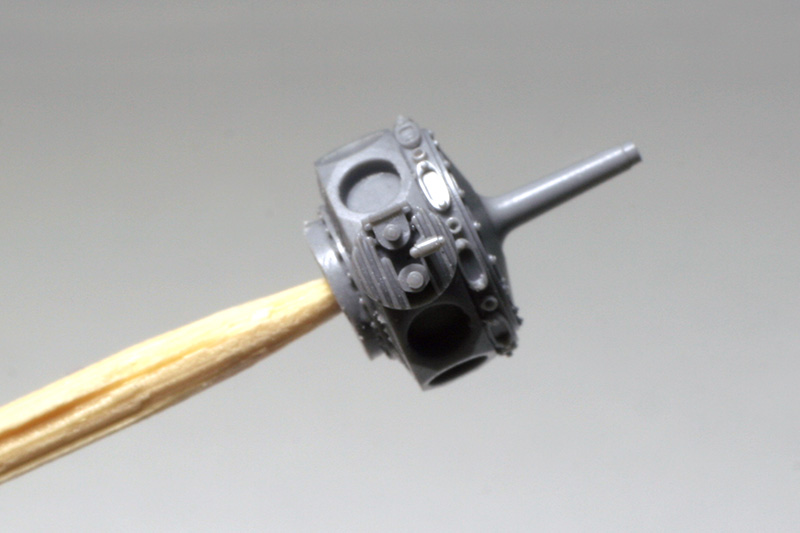
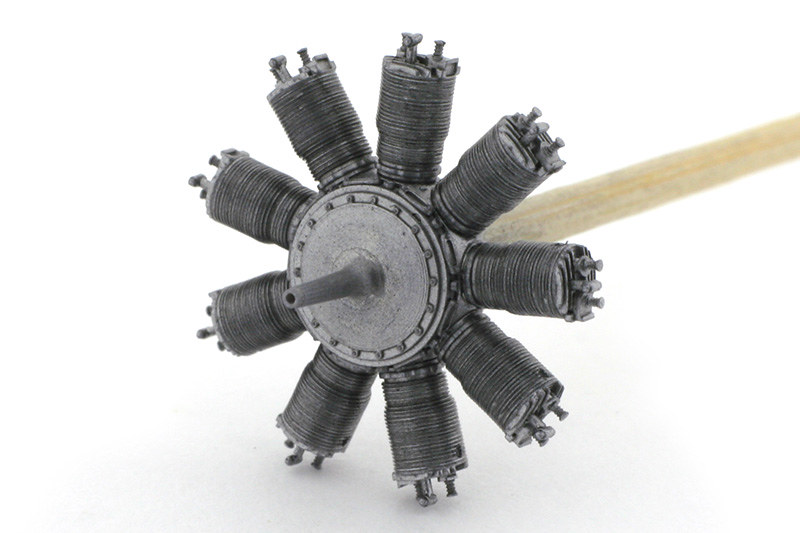
First, I remove the crankcase from it's casting block with a thin saw. Some crankcases have delicate details on their fronts that can be easily damaged, so care should be taken while handling these parts. After sawing the part off I drill a hole in it's back and insert a toothpick, which will help to hold the engine during the assembly.
 |
 |
Cylinders can be easily cut off with a razor blade. Once again, care should be taken not to break off the fragile detailing on top of a cylinder. It then can be mounted onto the crankcase. If the fit is tight enough, the cylinder can be positioned correctly without any glue. If not, a drop of Microscale Foil Adhesive or similar glue that produces a sticky surface can be placed into the crankcase recess and allowed to dry before inserting a cylinder. This glue holds a cylinder in place, while still allowing to move it. A cylinder should then be aligned correctly.
 |
 |
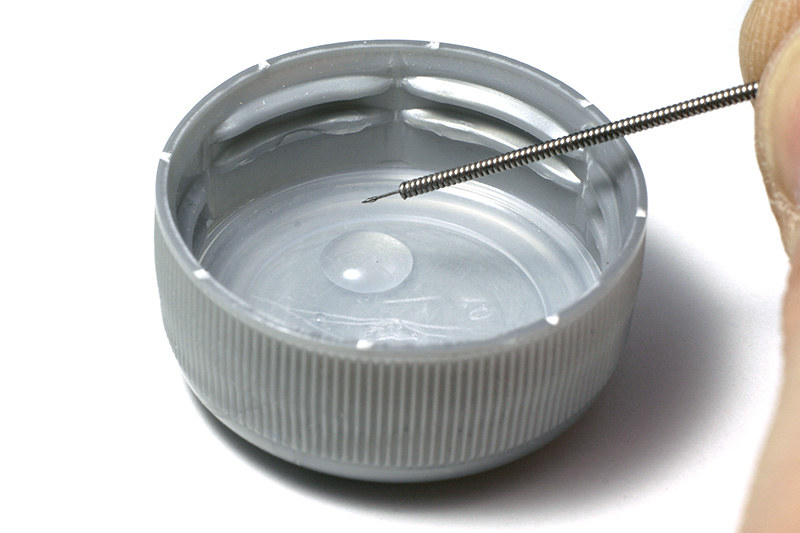
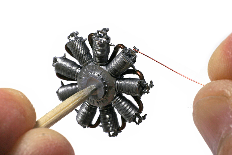
Now, with a cylinder in place, it can be fixed with a CA glue. I normally use Medium CA+ Zap-A-Gap, but any medium viscosity/speed CA can be used instead. I place a drop of a glue on any surface (it will stay liquid for a long time), dip a thin wire into it and then apply a glue with the wire to the gap between a crankcase and a cylinder, mostly to the rear and the sides of the cylinder, where the glue will be less visible. Excess CA can be removed carefully with a special debonder or even acetone, but this is rarely needed if a glue is applied carefully.
This technique of positioning a part with a foil adhesive or other sticky glue and then fixing it permanently with CA is used throughout the assembly.
 |
 |
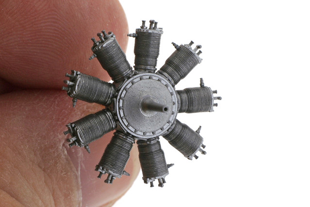
Now it's time to paint the parts. Assembled crankcase with cylinders, as well as all the other parts still on their casting blocks are airbrushed with appropriate shades of Alclad Lacquer.
 |
 |
 |
 |
Various weathering techniques can be employed to bring an engine to life. I use a fairly minimalistic approach which consists of applying a sort of wash to all the parts. I mix Future varnish with a little bit of water and add a tiny amount of Vallejo acrylic paint of dark, dirty brownish color. The resulting brew is mixed thoroughly, resulting in a semi-transparent dirty liquid. It's then generously applied to all the parts with a soft brush in just one pass and left to dry.
 |
 |
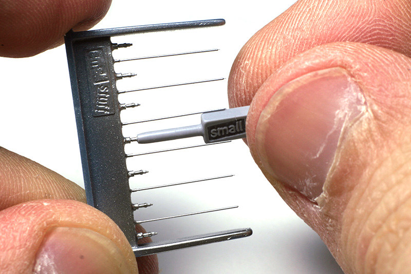
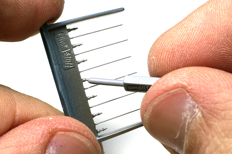
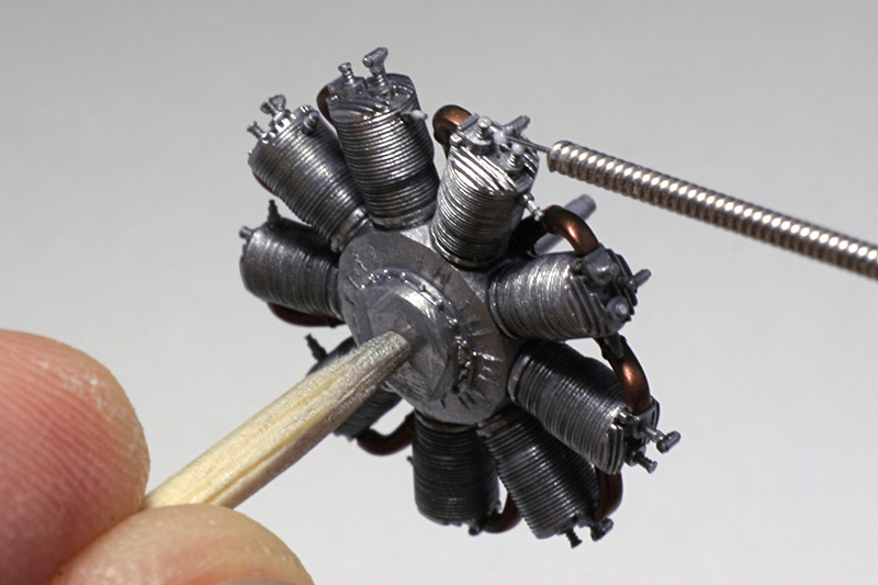
After that spark plugs can be mounted. To do that, first some foil adhesive is applied with a wire to the holes in the cylinders where spark plugs go and left to dry. A special tool provided in the kit is used to pick and install the spark plugs. It's tubular tip should be wet (personally I just lick it :) ) to hold the spark plug. It's then lowered onto the spark plug on it's casting block and used to brake a spark plug off and insert it into the hole in a cylinder, where it's held by the foil adhesive. Since the adhesive is flexible, a spark plug's position can be adjusted, and then it can optionally be fixed by applying a little Future (or the wash used in the previous step) with a tiny brush. While not being the strongest glue in the world, Future has an advantage of being almost invisible.
 |
 |
 |
 |
 |
 |
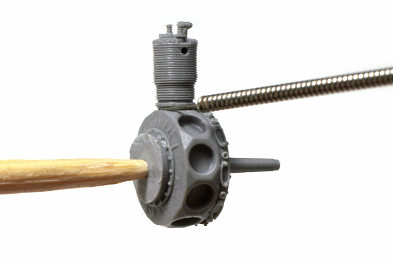
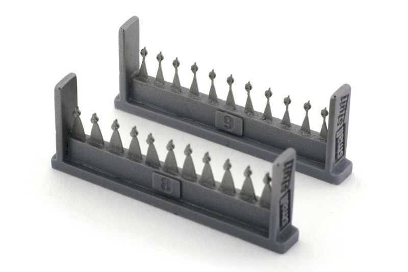
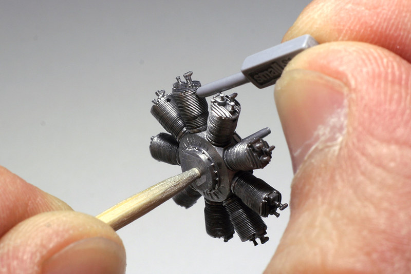
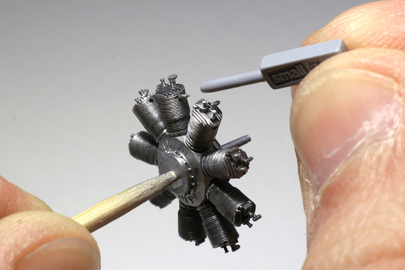
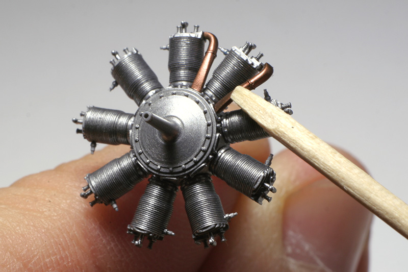
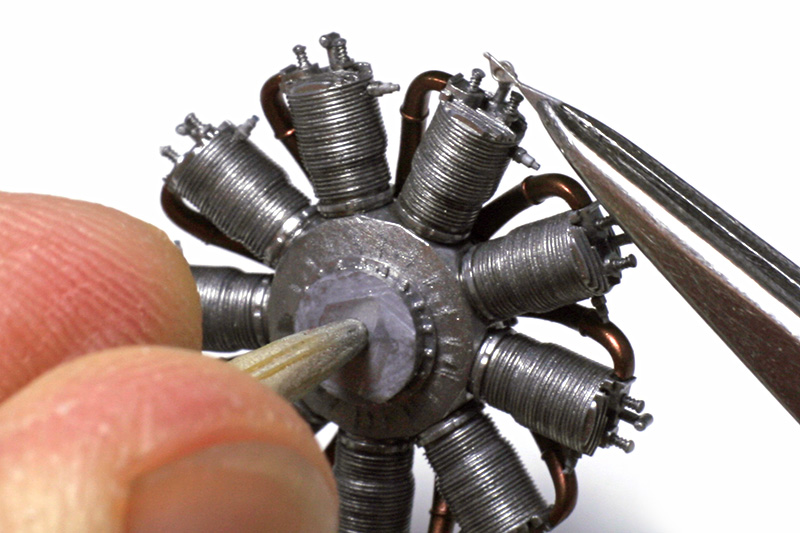
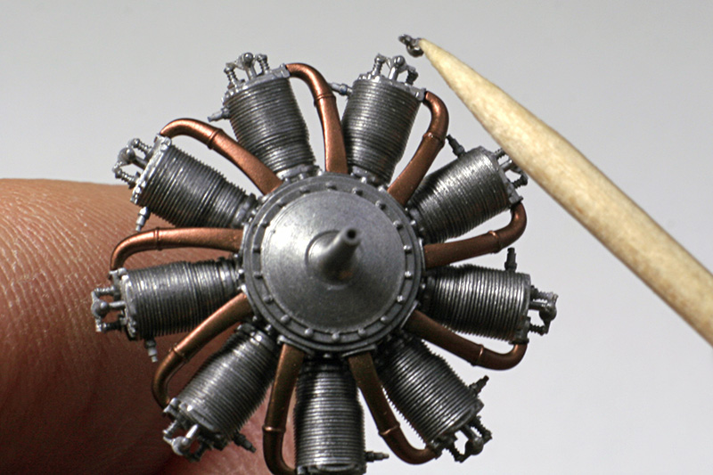
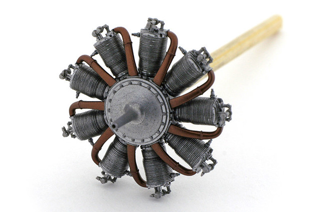
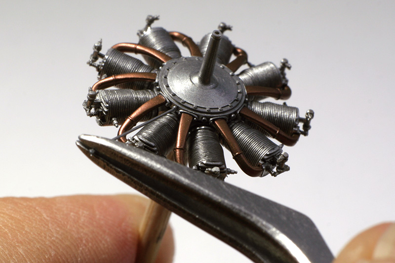
Now it's time to install the intake tubes, a beautiful and characteristic feature of Le Rhone 9C. Once again, foil adhesive is applied to the flanges on the crankcase and the cylinder where the tubes are connected and let dry. The tubes, already painted, can be broken off of the casting block and mounted into place, adjusted and then fixed with CA glue, applied to the gap between the tube and the cylinder, where it's less visible.
 |
 |
 |
 |
Next valve rockers are assembled. The technique is similar to the ones used in previous steps - foil adhesive is applied to the places, where part is to be attached, then the rocker is positioned and fixed with CA glue, applied with a thin wire. This time, however, it can be more convenient to cut the part together with a tab that connects it to the casting block. The rocker can be held by this tab with tweezers, and after it's secured with CA glue the tab can be carefully removed with a fresh razor blade.
 |
 |
 |
 |
A valve rocker lever is installed next, using a similar technique. I found it easier to remove the part from its tab with a razor before attaching it. The biggest challenge is not to lose a tiny part (although a couple of spares are provided). The part can then be picked with a wet toothpick, positioned and fixed with CA glue.
 |
 |
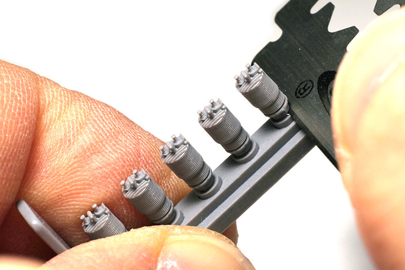
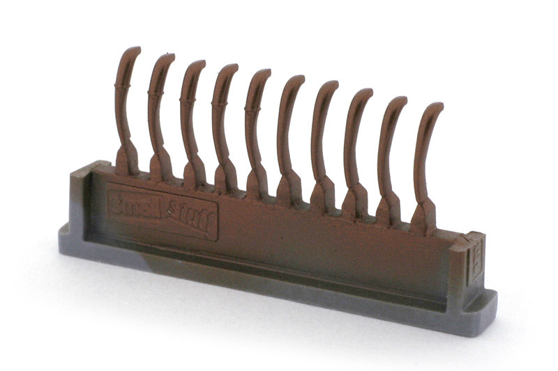
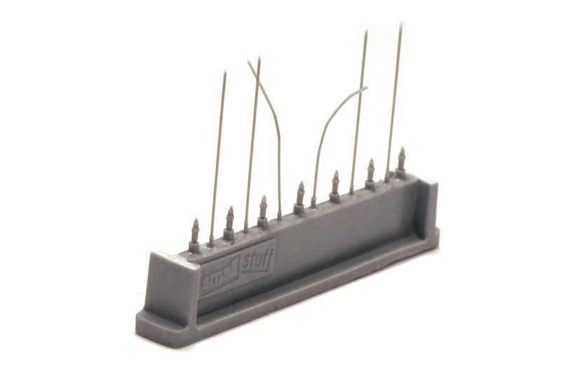
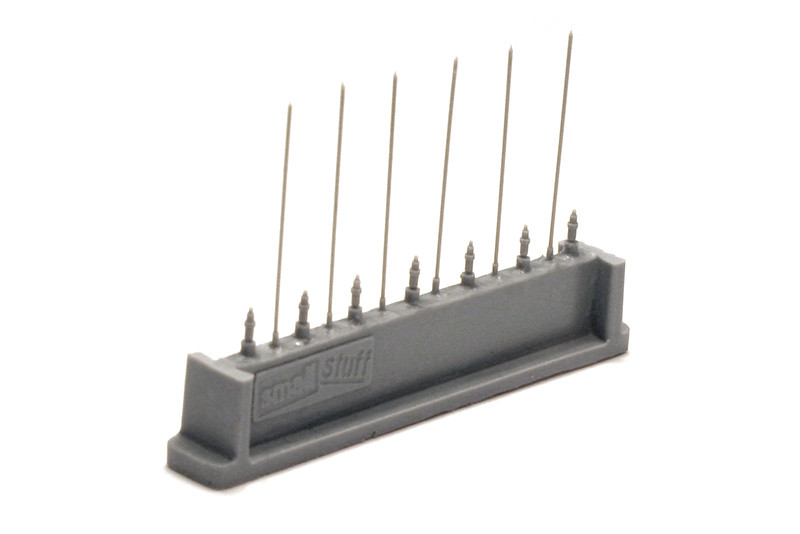
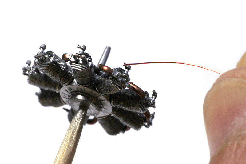
Last, we need to add valve rocker push rods. Each resin push rod is longer than needed, and is designed to be installed and then trimmed. The rods are very thin and flexible. Although unlikely, in case the set was packed inappropriately, there is a possibility that some of the rods are bent a little. This can be easily fixed by utilizing a very useful property of a urethane resin - when heated, a deformed resin part returns to its original shape. So, to repair a bent part we just need to heat the whole casting block by placing it vertically under an incandescent lamp or into an oven at about 70°-80°C (it's advisable to break off the protecting vertical blocks before heating the part). The parts in the first picture below were purposely bent by me (don't expect to see this level of deformation in your set, of course). The second picture was taken later after letting it sit under a 75 Watt lamp for about half an hour. Allow the part to cool completely before touching it.
 |
 |
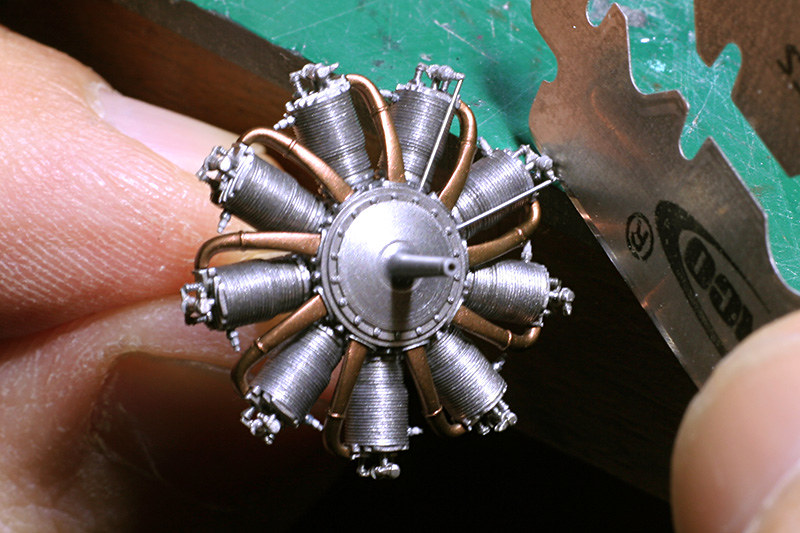
To install the push rods, first we apply some foil glue to the points where a push rod is attached. Then a push rod is cut at the base (it may also be a good idea to cut off it's very tip, which sometimes has imperfections), and first attached to the guiding ring on the crankcase. Then it's upper part is placed into the rocker lever fork. What's left now is to trim the excess of the push rod above the rocker lever, which is a little tricky. To do that the engine should be carefully positioned so that the push rod would lie flat on the surface. Then, using the rocker lever as a guide, the push rod is trimmed with a sharp razor. After that the push rod can be fixed by applying some Future to it's points of contact with the crankcase and the rocker lever with a very small brush.
 |
 |
 |
 |
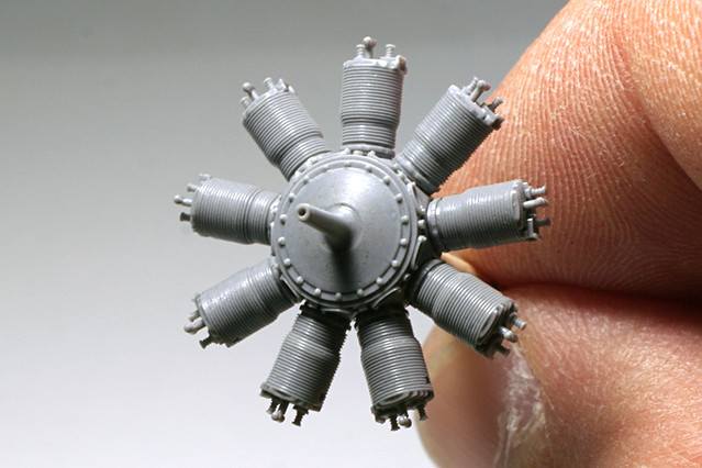
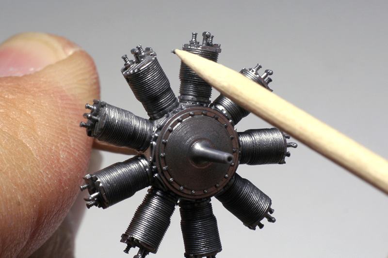
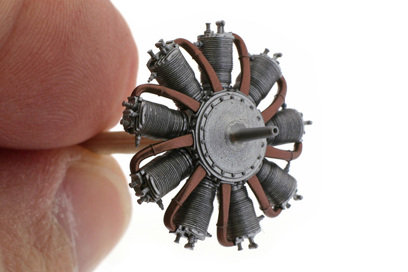
So there you have it - a reasonably detailed 1/48 Rhone. I hope this article will help those who wish to add our engines to their models get the most out of our sets with less hassle.
Eugeny Knupfer
I'm just starting to build your 1/72 Oberursel D.I for a Fokker D.II I'm making. I wasn't sure how to go about it, even with the instructions, but thanks to this in-depth tutorial I feel a lot more confident and comfortable about it. Thanks.
ReplyDeleteBeautiful, just beautiful.
ReplyDeleteWhat a shame that ww1 aircraft, especially in 72nd, are so scarce nowadays, Chorozy Modelbud excepted (ouch @ the price). Countless boring Messerschmitts but no Sopwith Pups, no Tabloids, no Bleriots, no Deperdussins...
A pity and a shame.